As with the Kef HTS3001SE I tested, I ordered a set of the Kef Q100 Bookshelf speakers in order to remove and review the raw Q100 driver itself. I really wanted to see how this coaxial design performed. Zaph had already tested this one but I wanted to do Klippel LSI testing on it to see how the suspension performed. He actually mentioned this in his writeup and I thought it would be cool to provide the results. Of course, since I had it on the test baffle I did some other standard measurements as well. The one I was interested in, but didn’t perform on the HTS3001SE driver was tweeter frequency response performance with movement of the woofer. I don’t necessarily have an easy way to test this so I did something a bit different: I used a 9v battery to statically ‘fix’ the woofer either in the coil out or coil in position and measured the response. I then compared this to the woofer at rest performance of the tweeter and did a direct comparison. This is discussed further below.
Let’s get on to the testing, but first … the obligatory pictures …

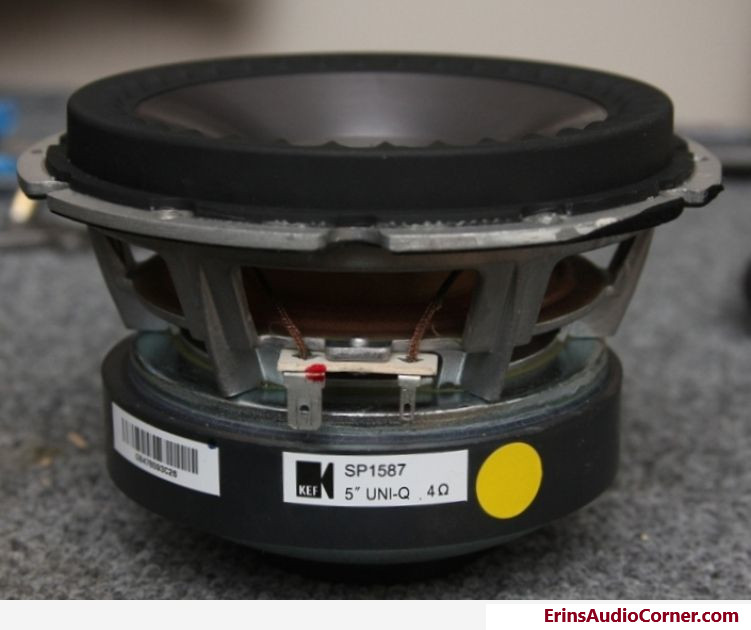
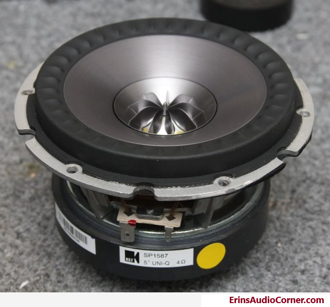
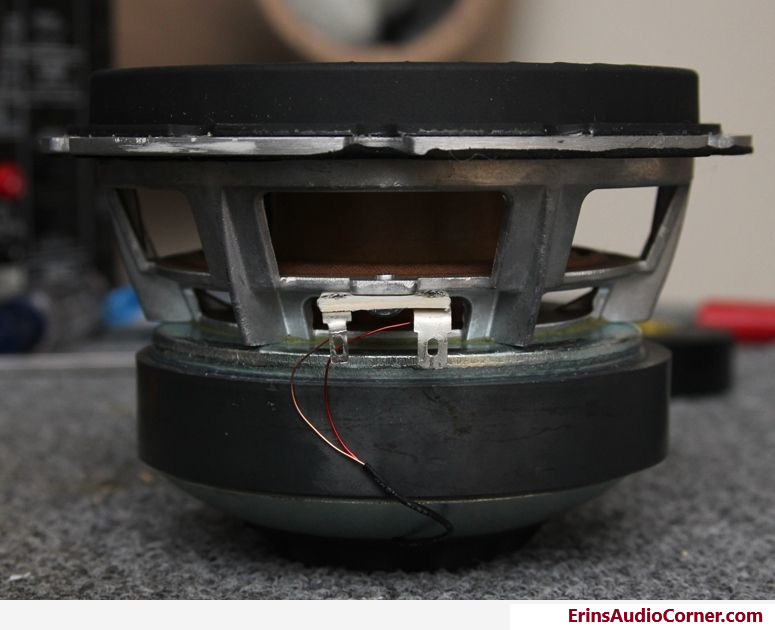
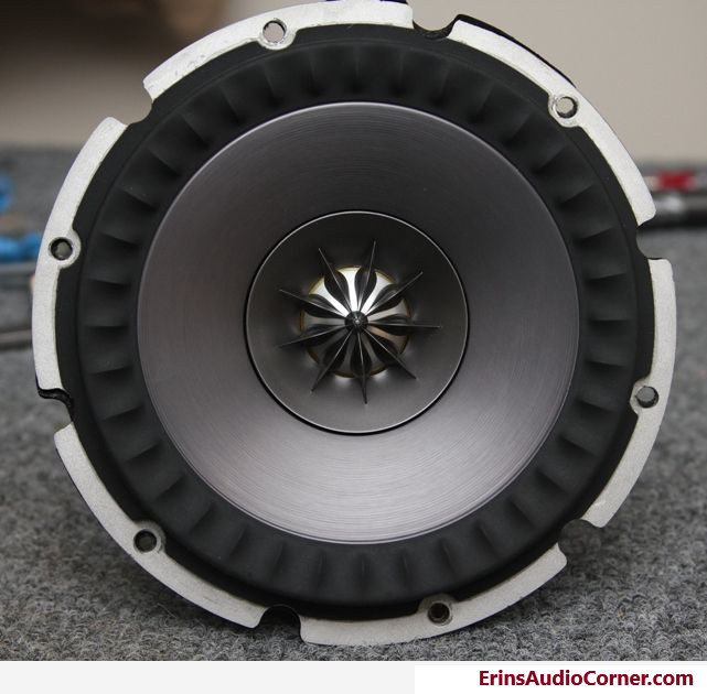
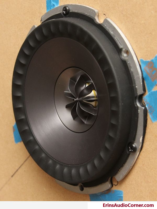
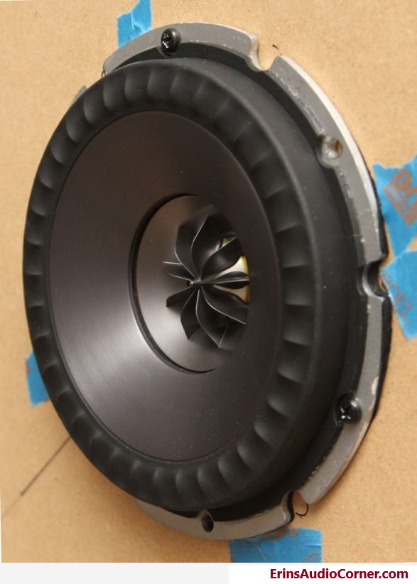
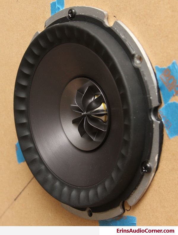
This driver is quite the little beast. A very large motor and pretty substantial surround make this one of the largest 5.25″ drivers I’ve personally seen. Although I didn’t weigh it, it is fairly heavy due to the woofer’s ferrite magnet as opposed to neodymium. This results in large and heavy. I can’t exactly measure the voice coil but comparing it to the tweeter assembly, it appears to be a few mm larger in radius so I’d estimate VC diameter at roughly 55mm. It is best to rear mount this driver given the very tall surround at approximately 12mm, but for the purpose of my test I front mounted it.
If you look at the ‘Tangerine’ waveguide/lens/whatever you want to call it, you’ll notice there’s actually a phase plug on the tweeter. The HTS3001SE does not have this.
For those who want to read about the Tangerine waveguide, click this link (PDF format). There’s also discussion on the radial ribbing of the other Uni-Q cones, which this driver doesn’t employ.
Raw Driver Physical Measurements
First off, given this isn’t sold as an individual driver, I have taken my own measurements. These are rough measurements taken with my not-so-recently calibrated calipers, but should be good within +/-1mm.
| Dimension | mm |
|---|---|
| Outer Diameter | 143 |
| Mounting Diameter | 120 |
| Mounting Depth | 83 |
| Effective Piston Diameter1 | 109 |
| Effective Piston Diameter2 | 60 |
| Flange Thickness | 0.34 |
| Mounting Tab Thickness | 0.65 |
| 1) Half surround to half surround; including space consumed by coincident tweeter. | |
| 2) Half surround to half surround; NOT including space consumed by coincident tweeter. | |
Test Results
To make things a bit easier to manage, I’ve broken down the test results in to two sections:
- Woofer Testing
- Tweeter Testing
Part I: Woofer Testing
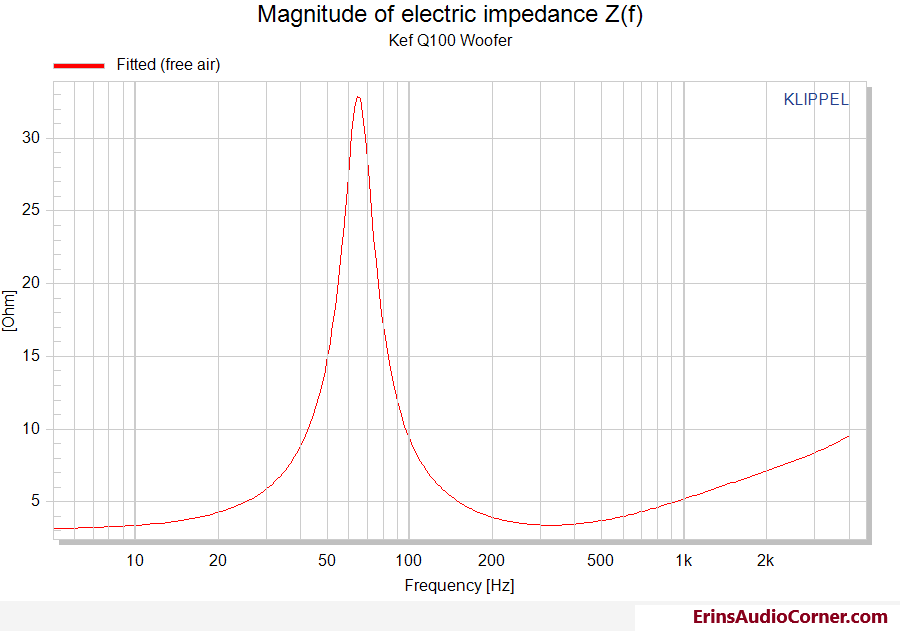
Woofer Thiele-Small Parameters and Impedance
Note: When determining the full suite of T/S parameters, the effective diameter of the driver is needed to calculate Vas, Bl, etc. Most of the time this can simply be measured by measuring the diameter of the driver from half-surround to half-surround since the motor must control the entire cone area. However, in this case, the entire cone does not move. Therefore, the effective diameter (and resulting Sd) is not the entire diameter of the driver. The effective diameter here is determined by subtracting the static tweeter assembly from the overall effective diameter of the woofer. See physical measurements section above for all values.
| Electrical Parameters | |||
|---|---|---|---|
| Re | 3.09 | Ohm | electrical voice coil resistance at DC |
| Le | 0.256 | mH | frequency independent part of voice coil inductance |
| L2 | 0.427 | mH | para-inductance of voice coil |
| R2 | 3.39 | Ohm | electrical resistance due to eddy current losses |
| Cmes | 318 | µF | electrical capacitance representing moving mass |
| Lces | 18.82 | mH | electrical inductance representing driver compliance |
| Res | 29.82 | Ohm | resistance due to mechanical losses |
| fs | 65 | Hz | driver resonance frequency |
| Mechanical Parameters | |||
|---|---|---|---|
| (using add. mass) | |||
| Mms | 12.834 | g | mechanical mass of driver diaphragm assembly including air load and voice coil |
| Mmd (Sd) | 12.108 | g | mechanical mass of voice coil and diaphragm without air load |
| Rms | 1.352 | kg/s | mechanical resistance of total-driver losses |
| Cms | 0.467 | mm/N | mechanical compliance of driver suspension |
| Kms | 2.14 | N/mm | mechanical stiffness of driver suspension |
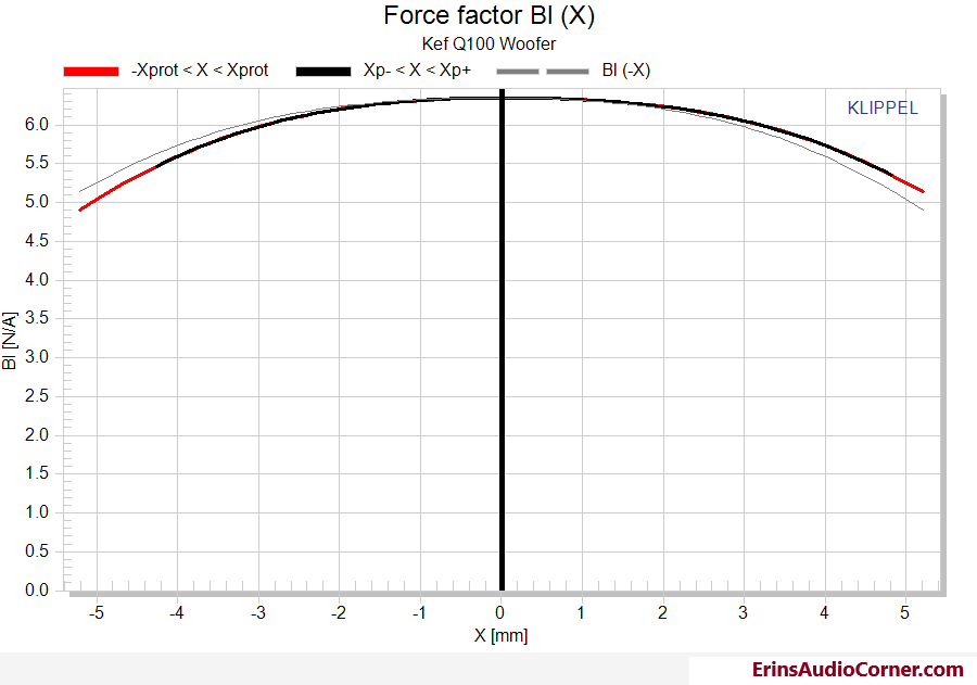
| Bl | 6.35 | N/A | force factor (Bl product) |
| Loss factors | |||
|---|---|---|---|
| Qtp | 0.365 | total Q-factor considering all losses | |
| Qms | 3.878 | mechanical Q-factor of driver in free air considering Rms only | |
| Qes | 0.402 | electrical Q-factor of driver in free air considering Re only | |
| Qts | 0.364 | total Q-factor considering Re and Rms only | |
| Other Parameters | |||
|---|---|---|---|
| Vas | 3.6615 | l | equivalent air volume of suspension |
| n0 | 0.241 | % | reference efficiency (2 pi-radiation using Re) |
| Lm | 86.02 | dB | characteristic sound pressure level (SPL at 1m for 1W @ Re) |
| Lnom | 87.14 | dB | nominal sensitivity (SPL at 1m for 1W @ Zn) |
| Sd | 74.46 | cm² | diaphragm area |
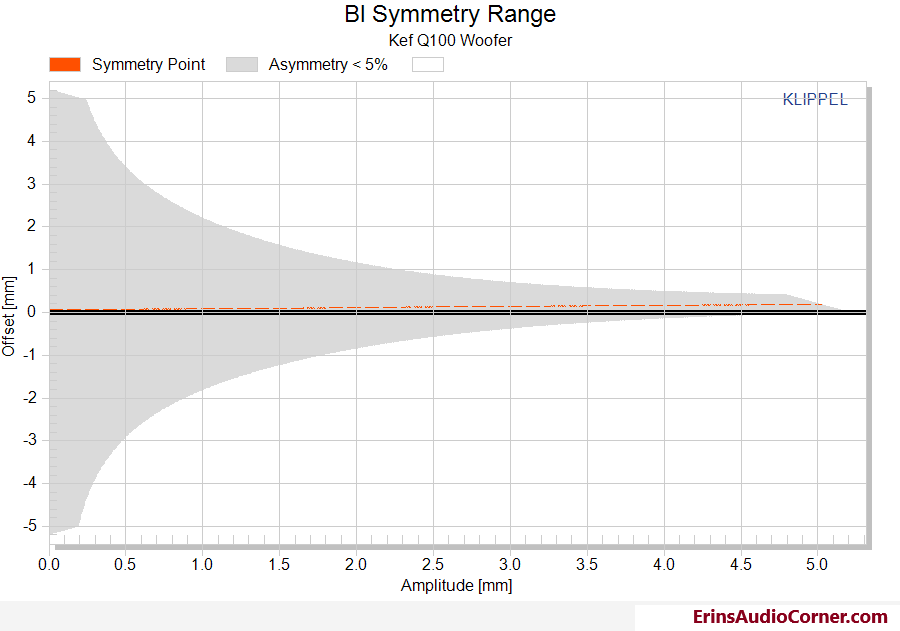
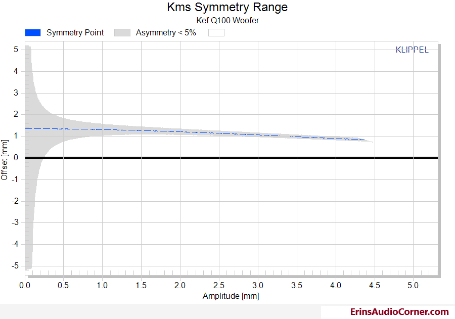
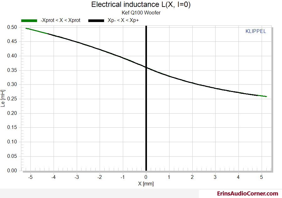
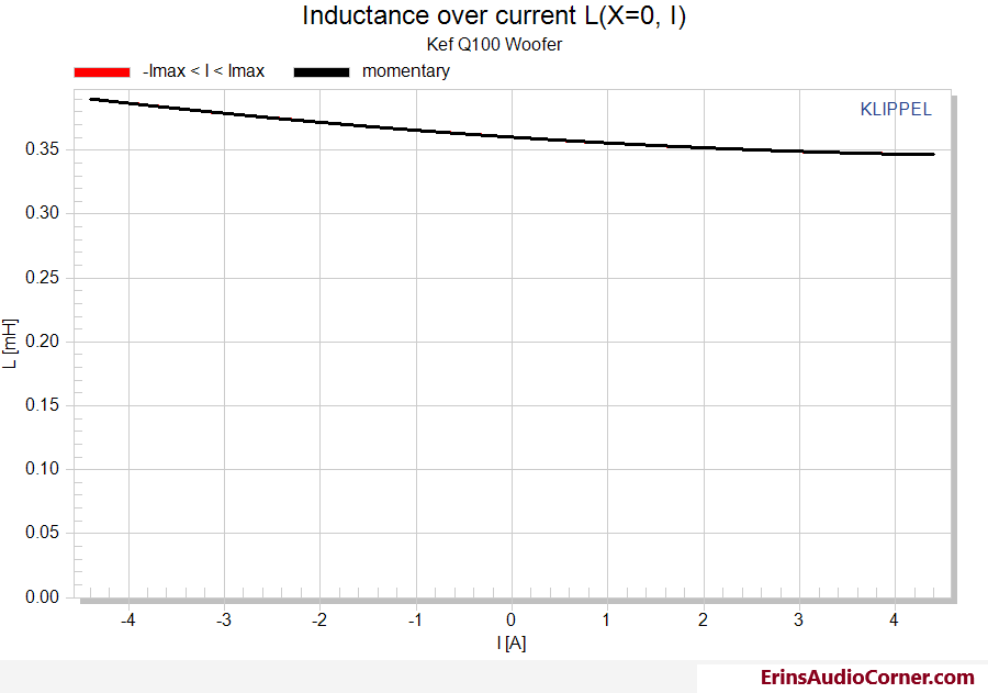
| Woofer Large Signal Analysis with Klippel’s LSI Module | |||
|---|---|---|---|
| Displacement Limits | thresholds can be changed in Processing property page | ||
| X Bl @ Bl min=82% | >4.2 | mm | Displacement limit due to force factor variation |
| X C @ C min=75% | 1.9 | mm | Displacement limit due to compliance variation |
| X L @ Z max=10 % | 2.8 | mm | Displacement limit due to inductance variation |
| X d @ d2=10% | 17.1 | mm | Displacement limit due to IM distortion (Doppler) |
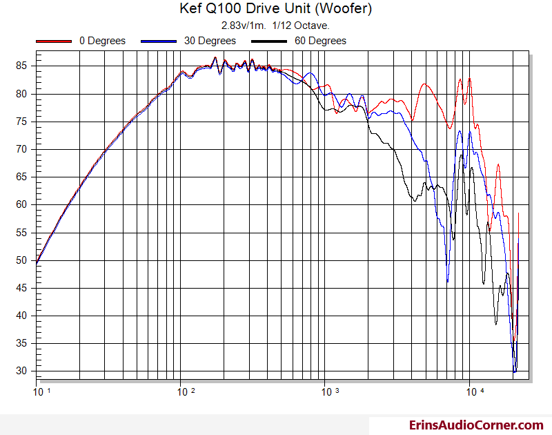
Woofer Frequency Response
Measured at 2.83v/1m. Stitched with a nearfield measurement at approximately 500hz.
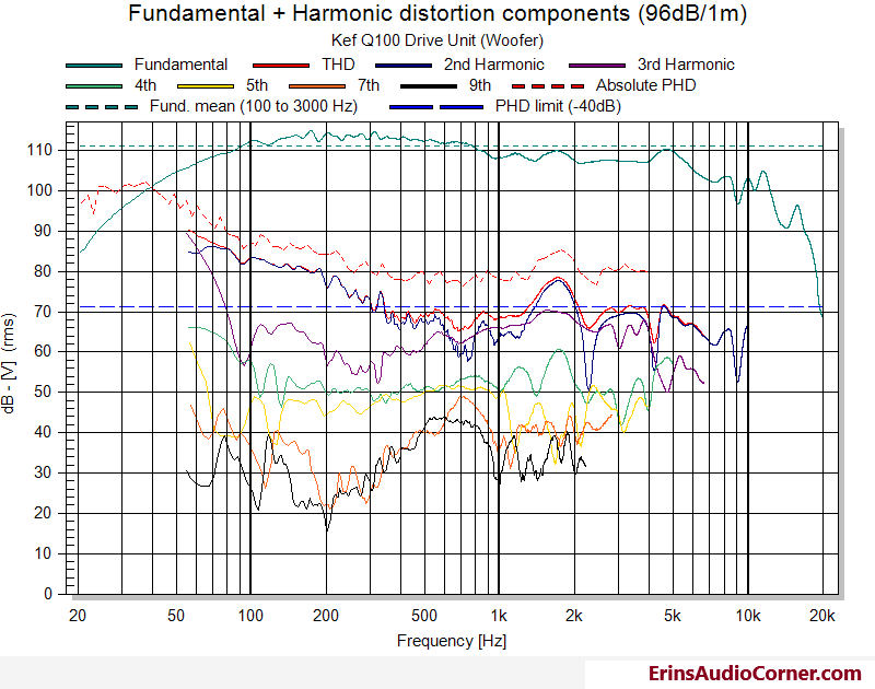
Woofer Harmonic Distortion
Part II: Tweeter Testing
Small Signal Parameters
| Electrical Parameters | |||
|---|---|---|---|
| Re | 2.84 | Ohm | electrical voice coil resistance at DC |
| Le | 0.018 | mH | frequency independent part of voice coil inductance |
| L2 | 0.011 | mH | para-inductance of voice coil |
| R2 | 0.5 | Ohm | electrical resistance due to eddy current losses |
| Cmes | 110 | µF | electrical capacitance representing moving mass |
| Lces | 0.28 | mH | electrical inductance representing driver compliance |
| Res | 1.09 | Ohm | resistance due to mechanical losses |
| fs | 902.6 | Hz | driver resonance frequency |
| Loss factors | |||
| Qtp | 0.491 | total Q-factor considering all losses | |
| Qms | 0.678 | mechanical Q-factor of driver in free air considering Rms only | |
| Qes | 1.769 | electrical Q-factor of driver in free air considering Re only | |
| Qts | 0.49 | total Q-factor considering Re and Rms only | |
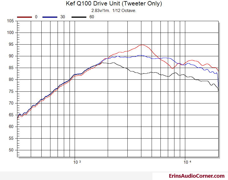
Tweeter Frequency Response
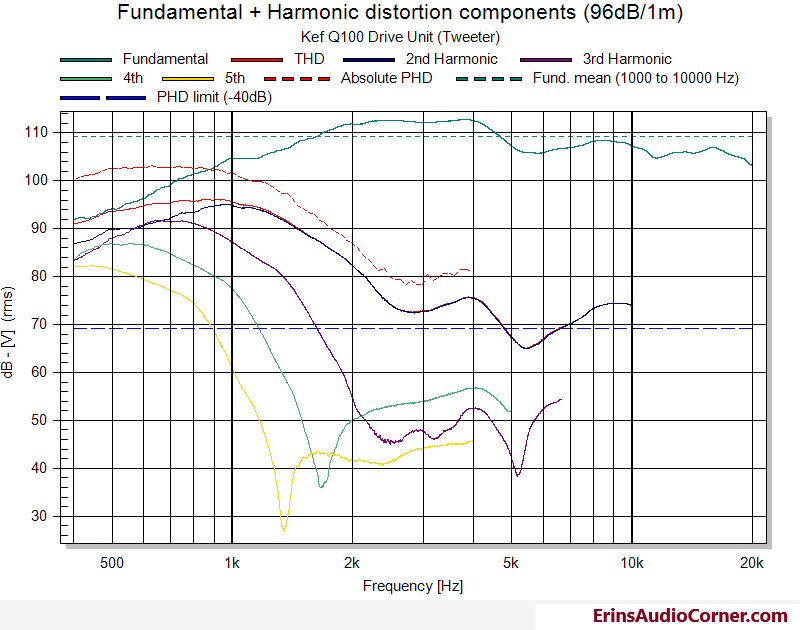
Tweeter Harmonic Distortion
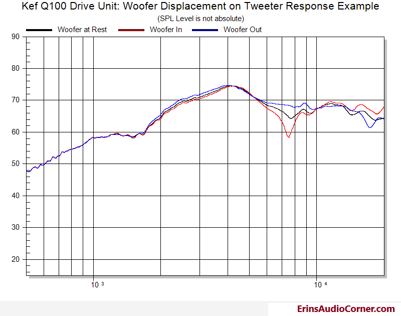
Tweeter Response vs Woofer Position
I thought it would be interesting to see how the position of the woofer cone impacts the frequency response of the tweeter. This matters when you’re listening to music and isn’t captured by a standard sine sweep. To measure this performance I simply connected a 9v battery to the woofer’s terminals in positive polarity, then negative polarity which resulted in an approximate +/-3mm shift in cone direction. I ran a sine sweep over the tweeter while the woofer was a) at rest, b) fixed out, and c) fixed in. The pictures below illustrate these different configurations.
Woofer at rest:
Woofer fixed out:
Woofer fixed in:
The following results are of the three positions discussed above overlaid on one another. The lines are labeled per the woofer position.
Note: The SPL level is not absolute here. I performed the test at the same volume level throughout but it is not intended to reference any set test paraemter such as 2.83v/1m or 1w/1m.
End
If you like what you see here and want to help me keep it going, there’s a Paypal Contribute button at the bottom of each page. Just provide what you can. Every little bit is truly appreciated.
You can also join my Facebook and YouTube pages via the links at the bottom of the page if you’d like to follow along with updates.
Thanks!